Adding Z-Wave Functionality To My ERV
I previously described the low-voltage wiring block on my ERV and how I intended to use it to hook up some smartness:
In a purely mechanical world, I could use a 3-position switch to make these connections, where the ON terminal is the common line and I switch it between LOW and HI (with the third position being OFF). But I do not want a mechanical solution, I want a smart solution.
I have not been able to locate a Z-wave 3-position (SPDT or SPCO) switch. Every switch and relay I’ve found in the Z-wave ecosystem is a simple SPST switch. Until I discover otherwise, I’ve devised a setup with two switches and a relay to emulate the behavior I’m looking for:
- The ERV’s ON line is switched by SW1 and connected to the COM terminal of Relay1.
- The ERV’s LO line is connected to the NO terminal of Relay1.
- The ERV’s HI line is connected to the NC terminal of Relay1.
- Relay1’s trigger is connected to a 12V DC line that is switched by SW2.
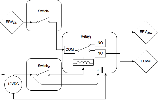
This means that:
- SW1 can be on or off, which controls whether the ERV is on or off.
- SW2 can be on or off, where on is High-speed and off is Low-speed operation.
- SW1 and SW2 are independent switches; they can be on or off in any combination without causing problems.
The end result is that the ERV is either ON or it is OFF, and when it is ON, it is either in LOW speed or it is in HIGH speed. This setup disallows the possibility that the ERV’s ON terminal is shorted to HI and LO at the same time; it is either one or the other.
Using The Right Switch
Most Z-wave switches are designed to switch the same load with which they’re powered, i.e., AC line voltage. This is fine for switching a light on or off, but not for switching the low-voltage loads on the ERV’s terminal block. I need a “dry contact” relay switch, one that separates the module’s power from the voltage it’s switching.
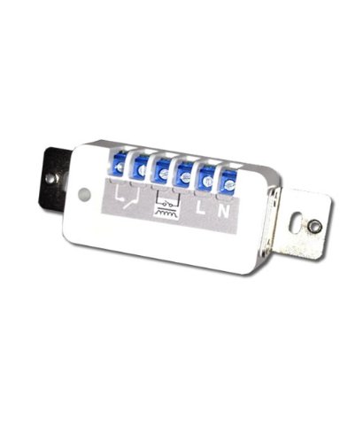
There aren’t many such devices in this category, so I bought two of these Remotec Zwave Dry Contact Fixture Modules. They include a manual pushbutton in addition to being Z-wave devices, they successfully separate their own power voltage from the switched voltage, and they’re low profile. You could install a blank faceplate over the top of these if you wanted and didn’t need access to the pushbutton.
In the utility room I installed a deep double-gang box, brought in some Romex from a nearby outlet and wired the switches up to main AC using their L (Line) and N (Neutral) terminals. Once powered up, I was able to join them to the Z-Wave network hosted by my SmartThings hub, and I gave these switches the names “ERV On/Off” and “ERV Hi/Lo”.
Note that these switches have two additional pairs of terminals: a pair illustrated as a switch, and a pair illustrated as a relay. The switch pair would allow me to attach an external switch to this switch. Presumably I could throw some 18/2 thermostat wire from here to somewhere else in the house and use a $0.59 toggle switch to operate this relay remotely. The use case here is to use Z-wave and the switch’s own button to operate the relay, so for now I’m leaving these terminals unconnected.
The other pair, illustrated as a relay, is where I need to connect the load I’m using this relay to switch. As described above, on SW1 this will be the ON line from the ERV on one terminal, and the COM terminal of Relay1 on the other. On SW2 this will be the 12V trigger going to Relay1.
First, I need to get the wires from the ERV to these switches.
Wiring it up.
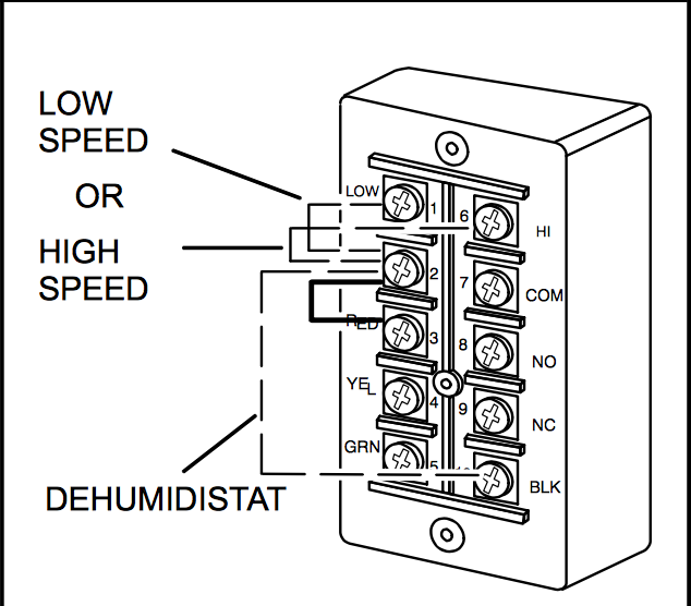
The ERV’s terminal block has a total of 10 terminals, but only a few of those are relevant to my project:
- RED/YEL/GRN are used to wire up the main controls, like the master on/off switch that the builder put in.
- COM/NO/NC are relay terminals. I could probably dream up an interesting use for these, but they’re designed to be wired to your Air Handler/Furnace Blower so that the ERV can turn on your blower fan.
- ON/LOW/HI/BLK are the only four terminals left, and of these I only need to concern myself with ON/LOW/HI. BLK is used to control the “dehumidistat” function, which I won’t use1.
It’s not a problem getting wires from the ERV to my switches; everything is in the same unfinished utility room, but I’m not going to make a direct connection.
Here’s what I do:
- Run a length of 18/5 thermostat wire from the ERV to my backer board. This backer board is where I have all my house wiring terminated, including security, network, and CATV cabling.
- Run another length of 18/5 t-stat wire from the switches to the backer board.
- Install a terminal block on the backer board and connect both t-stat wire runs.
This setup gives me continuity from the ERV to the switches while maintaining some flexibility at the backer board if I need to relocate or redesign anything.
At the ERV I connect wires to ON, LOW, and HI. The other two wires in the t-stat cable I leave disconnected for now. At the other end, I terminate all 5 wires to the block.
From the backer board to the switches is a little more complicated. I need to move not only the ERV continuity but also 12V DC to power the Relay1 I’ll be using to switch between LO and HI.
I have a lot going on on this backer board, including 12V DC, so I have that available. My 5/C wire is perfect for moving those three ERV signals and +/- 12V DC. I hook up three of the conductors to the matching terminals for ON/LOW/HIGH on the block and the other two to +/- from my 12VDC power source.
The Relay
In addition to the two Z-wave switches I have specified a need for a traditional Relay as Relay1. I am using one of these relays, a 12VDC opto-isolator 1-channel relay. It’s quite small and will tuck into the box behind my switches just fine. I’ve used one of these elsewhere to create a 12V-triggered power cable.
The relay is powered and triggered by 12VDC, and it has the expected COM/NO/NC terminals for switching its load.
On one end of the relay module there are three terminals: DC+, DC-, and IN. This is for connecting the power and the trigger to the relay. The opposite end of the module has the three relay terminals.
The way I wire this up is:
- DC+ from backer board to DC+ on module.
- DC- from backer board to DC- on module.
- LOW from backer board to NO on module.
- HI from backer board to NC on module.
- A jumper from SW1’s relay terminal to COM on module.
- A jumper from SW2’s relay terminal to IN on module.
Switch 2
The last piece of the puzzle is SW2, another of the Z-wave dry contact switches. This one will actually switch the 12VDC trigger going to the relay module. When off, the Relay will have NO shorted to COM, which has the ERV in Low-speed mode. When on, the relay will short NC to COM instead and switch the ERV to High-speed mode.
Like SW1, line voltage is applied to SW2 on its L and N terminals. DC+ from the backer board is connected to one of the relay terminals, and a jumper from the other relay terminal to IN on Relay1 completes the job.
Testing It Out
After powering everything up, I can test the solution using the physical buttons on each of the Remotec switches. Indeed, I can turn the ERV on or off or switch from low to high speed using the two switches and the (hidden from view) relay.
I’m now ready to start incorporating the Z-Wave functionality via SmartThings to make my dumb ERV smart!
The Future
This setup seems convoluted, and maybe it is. Maybe it’s a naive implementation of a 3-position switch in a Z-Wave network, but it works exactly the way I intended, so that’s a positive.
As I learn more and am exposed to new and different Z-Wave modules I might find opportunity to replace some or all of this setup. This single Z-wave relay unit from FortrezZ for instance might be able to do the same job, but it wasn’t yet on the market when I began implementing my solution. That’s fine; it would free those dry contact switches for other purposes, and there’s never a shortage of applications for a good dry contact switch.
Like most things, this project is an ongoing concern, and iterative or incremental improvements are expected.
-
The “dehumidistat” is a feature that aims to reduce indoor humidity during the heating season not by actually dehumidifying anything but by running the system more often when it’s cold outside and wet inside. I don’t think it’s even an ERV feature; I think it’s only present on HRVs. Excess humidity during the winter is not a problem anyway. ↩